
Slewing Bearing Installation Guide: Flatness, Bolt Torque & the Soft Zone
Most slewing bearing failures are installed, not manufactured. By the time a ring shows brinelling at the raceway edge, cracked bolt holes or a wiped gear flank, the bearing itself is usually innocent. The damage was set in during the first afternoon it was mounted — a mounting face that was not flat enough, bolts torqued by feel, or a soft zone pointed straight at the drive pinion. This guide covers the installation steps competitors list but never quantify.
Selection and installation are one job split across two moments. The slewing bearing selection guide gets the size right on paper; this guide keeps that size right once the ring is on the machine. A perfectly selected ring mounted onto a twisted pedestal will fail exactly like an undersized one, and the failure will look the same to whoever has to explain it to the customer.
1. Why installation, not the bearing, decides the life
A slew ring is normally the most precisely made component in the joint, and usually the softest. Its raceways are ground or hardened to a fraction of a millimetre; the structure it bolts to is fabricated steel. The ring is designed on the assumption that whatever it sits on is stiffer and flatter than the ring. Break that assumption and the ring deforms into the shape of its mounting, the load concentrates onto a fraction of the intended contact area, and the raceway brinells locally while the bolts fret.
The failures that reach our desk most often are interface failures:
- Mounting face out of flatness — the ring is dragged into the shape of a warped plate.
- Bolts under-preloaded or torqued unevenly — the joint opens under load, the ring rocks, the bolts loosen.
- Soft zone in the wrong sector — the lowest-hardness band of the gear sits where the pinion loads it hardest.
- Clearance never checked — a bad fit is discovered only when the gear howls or the structure cracks.
None of these is a bearing defect. All of them are caught at installation. The rest of this guide quantifies the four checks.
2. Mounting-face flatness — by diameter, not by guess
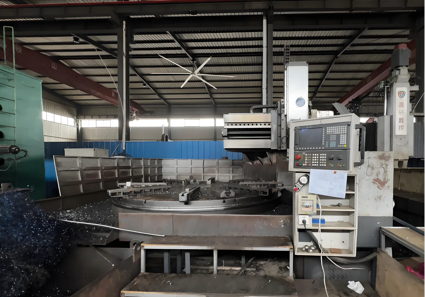
The single most common installation fault is bolting a precision ring to a face that is flat “enough” in the engineer’s head but not on the drawing. Flatness tolerance is size-dependent: a small ring tolerates a few hundredths of a millimetre; a four-metre ring needs a looser but still controlled figure because the structure naturally deflects more.
| Ring pitch diameter D | Typical flatness tolerance (total) | Why it grows with D |
|---|---|---|
| D ≤ 500 mm | 0.10 mm | Small fabrications hold tight easily |
| 500 < D ≤ 1 000 mm | 0.15 mm | Weld distortion starts to matter |
| 1 000 < D ≤ 1 500 mm | 0.20 mm | Plate weight induces sag |
| 1 500 < D ≤ 2 000 mm | 0.25 mm | Support structure deflection rises |
| 2 000 < D ≤ 3 000 mm | 0.35 mm | Large fabricated beds need machining |
| 3 000 < D ≤ 4 000 mm | 0.45 mm | Stiffness, not just flatness, must be verified |
| D > 4 000 mm | 0.55 mm | Confirm against the supplier’s figure for the ring |
These are guidance figures drawn from common supplier practice. The value on the drawing or in the mounting instruction for the specific ring always governs — never substitute a generic number, because the tolerance is set against that ring’s section height and bolt layout.
To measure it, span the bolt circle with a precision straightedge and run a dial gauge (or feeler gauges) across the gap at several diameters and rotations; on large rings a continuous scan with a dial gauge on a trammel is worth the time. The face must be flat across the bolt circle, not just locally clean. Paint, spatter, a stray weld bead or a gasket offcut under one bolt is enough to tip the ring.
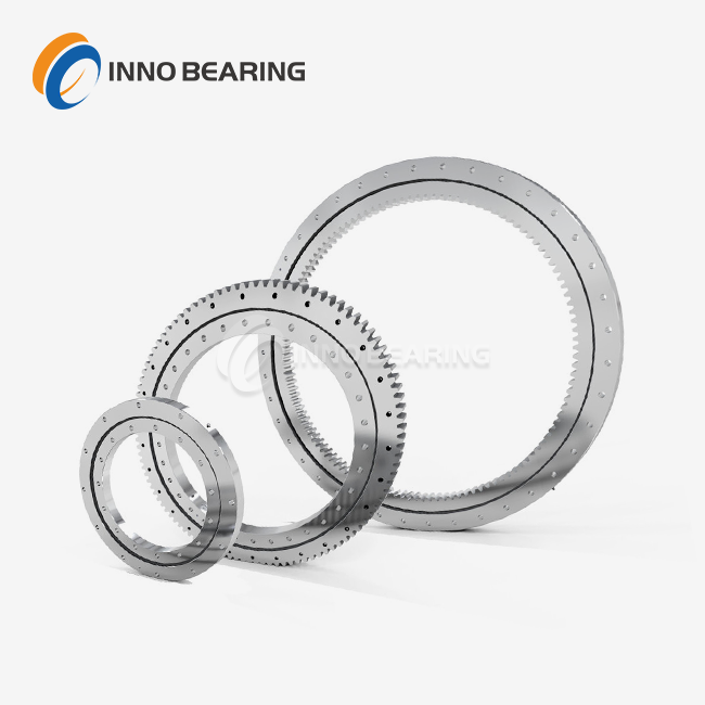
Where duty permits, the four-point contact ball slewing bearing is the most economical starting point; the broader single-row and double-row ball families cover lighter and heavier general duties. But economy does not mean tolerance-free — the same flatness rule applies to a ball ring as to a three-row roller. The lighter the ring, the more a bad face shows up as noise and play.
3. The soft zone — what it is and where it must point
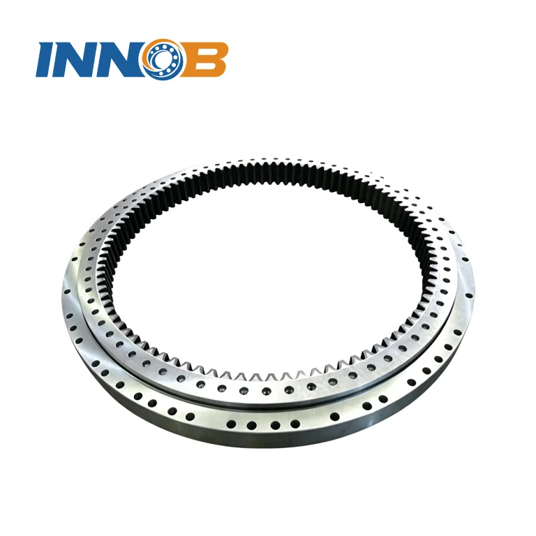
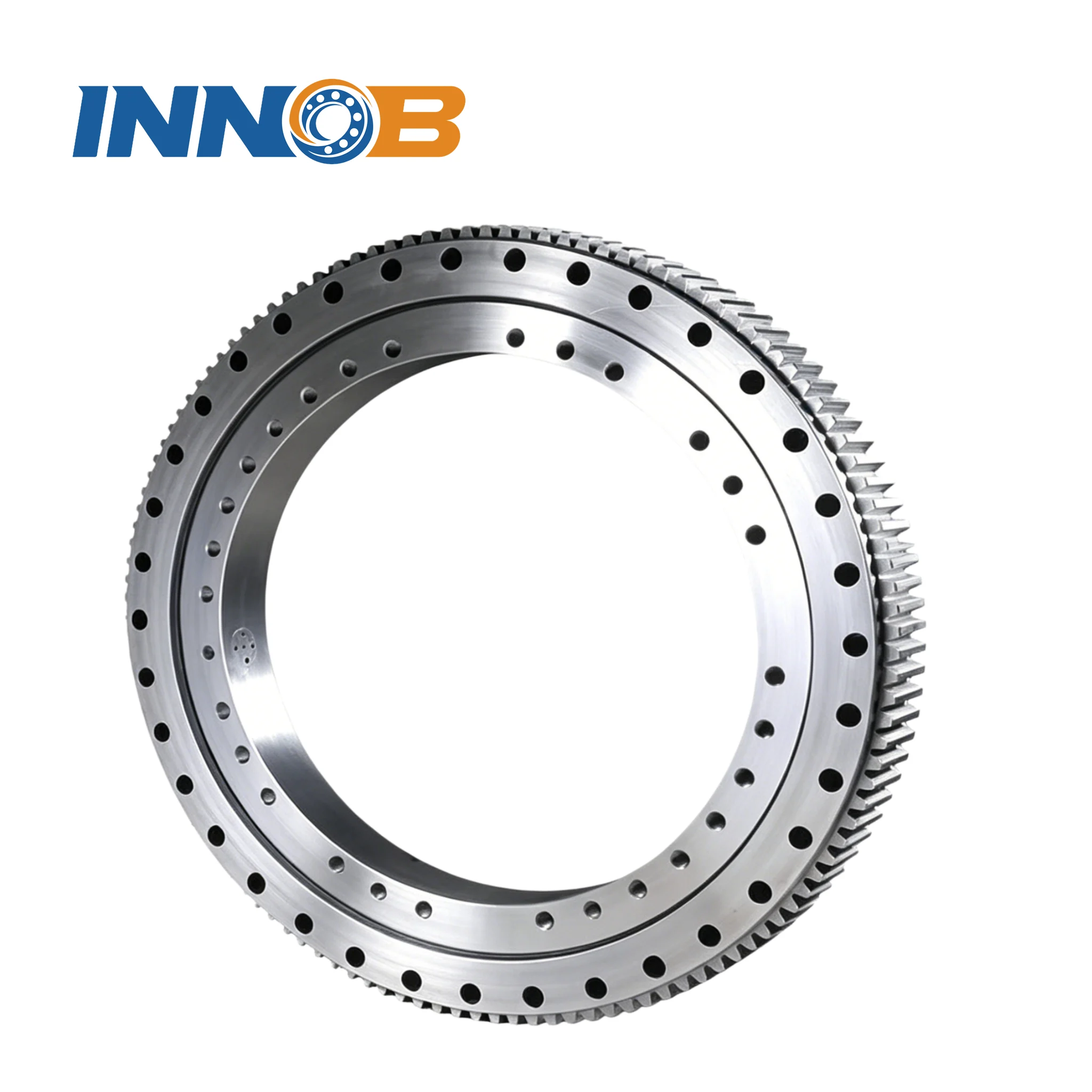
The gear teeth on a slewing ring are induction hardened for wear resistance, but the hardening coil has a start and a stop. Where the coil’s hardened band overlaps itself there is a narrow zone of reduced flank hardness — the soft zone. Suppliers mark it with an “S” stamped or painted on the gear, or a coloured band on the raceway.
This is the weakest part of the gear. The rule is simple and non-negotiable:
Place the marked “S” sector of the ring
in the direction of LEAST load —
the side AWAY from the maximum tilting moment.
Example: a luffing crane whose worst moment is
at full boom reach must have the soft zone facing
the stowed / minimum-reach side, never the load side.
If the soft zone is pointed at the drive pinion’s peak-load sector, the pinion will keep loading the lowest-hardness band of the gear every cycle, and that band will pit and spall first. Get the orientation right and the pinion always peaks on fully hardened flank. The orientation is marked on the ring and must be transferred to the machine drawing before bolting — it is the one step that cannot be corrected afterwards without taking the ring off.
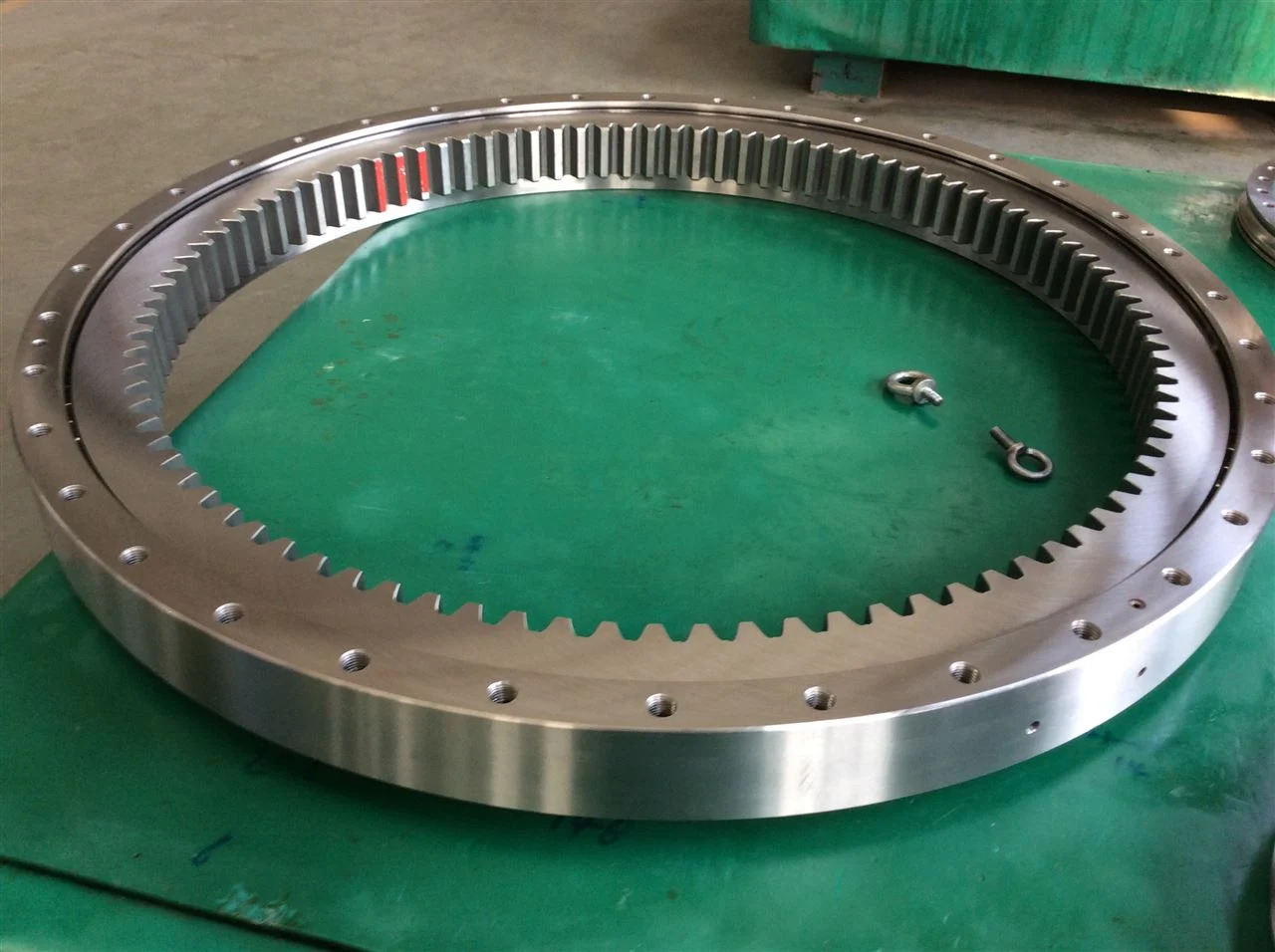
On an internal gear ring the soft zone sits on the inside tooth flank; on an external gear ring on the outside flank. The location is the same idea either way — find the mark, point it at the least-loaded sector. A no-gear ring has no hardened tooth band and therefore no soft zone to orient, but every other check in this guide still applies.
4. Bolt preload torque — the numbers competitors omit
Slewing bearing bolts are high-strength — normally property class 10.9, sometimes 12.9 for the heaviest rings, occasionally 8.8 on small lightly loaded rings. They are preloaded, not just nipped up: the clamping force from the preload, not the bolt shank in shear, carries the load. Torque is the practical way to reach that preload.
Torque relates to preload through the joint’s torque coefficient K (roughly 0.20 for a lubricated, medium-finish thread and head). The table below gives illustrative preload and torque for common diameters at K = 0.20. Treat them as sanity checks against the supplier’s figure, which always governs.
| Thread | 8.8 preload / torque | 10.9 preload / torque | 12.9 preload / torque |
|---|---|---|---|
| M16 | 70 kN / 225 N·m | 103 kN / 330 N·m | 121 kN / 385 N·m |
| M20 | 110 kN / 440 N·m | 161 kN / 645 N·m | 189 kN / 755 N·m |
| M24 | 158 kN / 760 N·m | 232 kN / 1 115 N·m | 272 kN / 1 305 N·m |
| M27 | — | 302 kN / 1 630 N·m | 354 kN / 1 910 N·m |
| M30 | — | 369 kN / 2 215 N·m | 432 kN / 2 595 N·m |
| M36 | — | 538 kN / 3 870 N·m | 630 kN / 4 530 N·m |
Two things move these numbers in real life, so never bolt from this table alone. First, lubrication: a dry or galvanised thread can need 30–50% more torque for the same preload, and an over-lubricated one less, which is why suppliers specify the thread condition. Second, grade: a 12.9 bolt at an 8.8 torque is dangerously under-preloaded; an 8.8 bolt at a 12.9 torque snaps. Match the torque to the actual bolts in the bag.
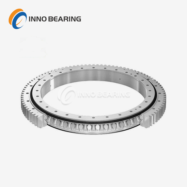
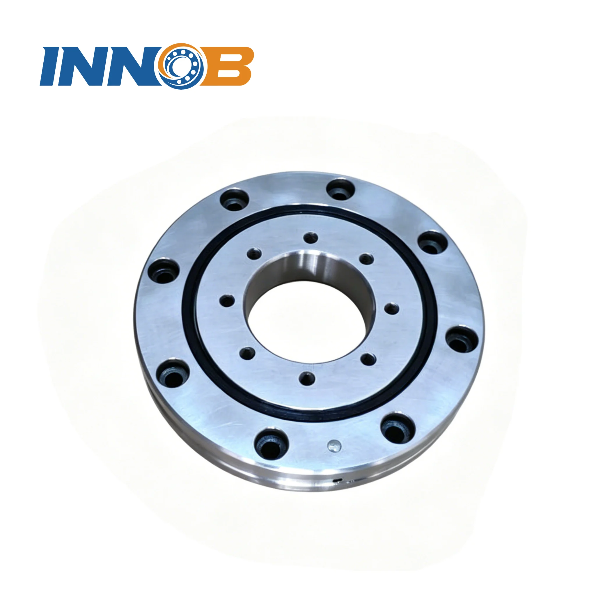
A cross roller ring carries high moment in a slim section, which makes a correctly preloaded, evenly torqued joint even more critical — there is little section to absorb a face that is not flat or a bolt circle that is not evenly clamped.
5. Tightening procedure — star pattern, in stages
How you torque matters as much as what torque. Two rules:
- Star (cross) sequence. Tighten bolts in a cross pattern across the diameter, not in a circle around the ring. A circular pass drags the ring down on the first side and cocks it; a star pattern seats it evenly.
- In stages. Take the joint to roughly 30%, then 60%, then 100% of final torque in separate passes. The joint settles between passes, so the final pass lands every bolt at the same preload.
| Pass | Torque as % of final | Purpose |
|---|---|---|
| 1 | ~30% | Draw the ring down, seat the interface, squeeze out air gaps |
| 2 | ~60% | Settle the joint before final clamp |
| 3 | 100% | Reach design preload evenly across the circle |
| Check | What to measure | Acceptance |
|---|---|---|
| Gear mesh clearance | Feeler gauge between pinion and ring gear at several mesh positions | Within the figure in the mounting instruction; consistent around the circle |
| Radial runout | Dial gauge on the geared / outer race as the ring is rotated | Within the stated runout limit for the ring |
| Local gap | Feeler under the ring at the bolt circle | No gap a feeler will enter; ring fully seated on the face |
A local gap you can slip a feeler into means the face is not good enough and the ring must come back off — far cheaper now than after the structure has cracked. A runout outside the limit means the ring is distorted and will wear unevenly. The gear mesh figure matters because too tight binds the drive and too loose hammers the teeth; both shorten gear life.
7. First fill lubrication
Grease the raceway and the gear before or at first commissioning so the first rotation purges any transit contamination, then set the relubrication interval from the duty rather than the calendar. A ring indexing continuously in a dusty yard and one rotating a few degrees twice a day on a positioning drive need very different regimes, and “when we remember” is not a regime. Marine, abrasive and hot environments justify more frequent attention and, where the duty is aggressive, fluoroelastomer seals over standard nitrile.
8. Installation checklist — the faults worth avoiding
- Accepting a mounting face that is “flat enough” without measuring it against the ring’s stated tolerance
- Measuring flatness locally instead of across the whole bolt circle
- Pointing the soft zone at the maximum-moment sector instead of the least-loaded one
- Using the torque table instead of the supplier’s specified figure for the actual bolt grade and lubrication
- Mixing bolt grades, or reusing bolts that have been stretched
- Torquing in a circle, or in a single pass, instead of a star sequence in stages
- Using spring washers in a preloaded joint
- Skipping the first re-torque after run-in
- Never checking gear mesh, runout or local gap before loading the machine
- Installing from memory instead of from the mounting instruction supplied with the ring
On that last point: where the whole rotation package is being replaced rather than just the ring, an integrated slew drive bearing removes the gear-matching and soft-zone risk entirely, because the pinion, housing and ring are supplied and tested as one assembly and the orientation is fixed at the factory.
9. What to confirm with your supplier before you mount
Every figure above is size-dependent, so the mounting instruction that ships with the ring is the document that governs. Before the ring leaves the crate, confirm these with the supplier for the specific size:
- Mounting-face flatness tolerance for the pitch diameter of the ring
- Bolt grade, diameter, quantity, hole pattern and the specified torque and lubrication
- The soft-zone mark location and the orientation rule for your load direction
- Gear mesh clearance and radial runout acceptance limits
- First-fill grease type and the relubrication interval for your duty
INNO BEARING manufactures slew rings from 200 mm to over 5 000 mm, with vertical lathes in-house to 5 m, and supplies a mounting instruction with every ring covering the flatness, bolt and clearance figures above. Send your interface drawing and load direction to [email protected] and we will confirm the installation data for the ring you are fitting.
10. Frequently asked questions
Related reading
Installation only matters because selection came first: the slewing bearing selection guide shows how to build the load case, combine the tilting moment and size against the static load curve, and the same load-first discipline appears on the mill side in the rolling mill bearing selection guide. For the machines these rings fit, the excavator slewing bearing, tower crane slewing ring and large diameter slewing bearings ranges cover most of the duty classes above.