
Slewing Bearing Selection Guide: How to Build the Load Case, Calculate the Tilting Moment and Size a Slew Ring That Lasts
Most slewing bearings are not selected — they are copied. An engineer replaces a failed ring with “the same one, but this time from a cheaper supplier”, inherits somebody else’s assumptions, and discovers eighteen months later that the replacement failed in exactly the same way. The original failure was rarely the ring’s fault. It was a selection fault.
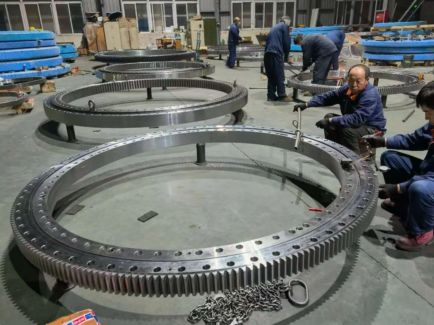
Slewing bearings do not behave like the standard rolling bearings most engineers are trained on. They turn slowly, they often oscillate rather than rotate, and the load that actually governs their size is usually not the machine’s weight but the leverage created when that weight hangs off the end of a boom. Get those two ideas straight and the rest of the selection becomes a sequence of checks rather than a guess.
This guide runs through the selection in the order it should be done: build the load case properly, combine it correctly, size against the static load curve rather than a fatigue life figure, pick the type, then check the gear and the bolted joint. There is a full worked example in section 5, because that is the step most published guides skip.
1. What makes a slewing bearing different
A slew ring typically rotates below 10 rpm, and on many machines it never completes a full revolution at all — it oscillates back and forth through 90° or 270° within a working arc. Rolling contact fatigue, the failure mode behind the familiar L10 rating, needs a large number of stress cycles to develop. A bearing that indexes a few times an hour may accumulate fewer load cycles in ten years than a conveyor pulley sees in a month.
So fatigue life is usually not what limits the design. Three other things do:
- Static capacity — the raceway must not brinell or permanently deform under the peak load, which is why suppliers publish a static load curve rather than a dynamic life rating.
- Structural stiffness — the ring is designed on the assumption that whatever it is bolted to is stiffer than the ring itself. If it is not, the ring deforms into the shape of its mounting and no amount of bearing capacity will save it.
- Peak combined load — a slew ring rarely sees axial, radial and moment loads one at a time. It sees them simultaneously, and the combination is what has to fit under the capacity envelope.
The practical consequence: selecting a slewing bearing is mostly about getting the load case and the interface right. The catalogue lookup comes last, not first.
2. Build the load case — three numbers, not two
Every slewing bearing selection starts with three simultaneous values at the most heavily loaded position in the duty cycle:
| Symbol | Load | What it actually is on the machine |
|---|---|---|
| Fa | Axial load | Vertical force along the axis of rotation — structurally dead weight plus payload, minus whatever is carried by other supports |
| Fr | Radial load | Horizontal force perpendicular to the axis — swinging loads, wind, braking reaction, digging resistance |
| M | Tilting moment | The turning effect of loads acting away from the axis — boom reach, offset payload, digging force at the bucket |
The single most common error at this stage is to take the maximum value of each load independently and add them together. Max Fa happens with the boom tucked in; max M happens with the boom at full reach carrying a load. They do not occur together, and treating them as simultaneous produces a genuinely expensive answer — you will buy a ring two sizes too big.
What you want is the simultaneous worst case: scan the duty cycle, find the position where the combination is most demanding, and record Fa, Fr and M at that instant. Then repeat for the second and third worst positions, because the load curve is not linear and the true worst case for a given ring size may not be the position with the highest moment.
Then apply a static safety factor
Multiply the service loads by a static safety factor fs appropriate to the machine class and to how well you actually know the duty. Values in the ranges below are widely used in the industry; treat them as starting points and defer to your supplier’s recommendation and the applicable machine standard.
| Machine class | Typical fs | Why |
|---|---|---|
| Mobile equipment, well-documented duty (excavators, loader cranes) | 1.10 – 1.40 | Load spectra measurable, duty cycle understood |
| Tower cranes, manned lifting platforms | 1.25 – 1.45 | High consequence of failure, dynamic hoist effects |
| Port, deck and offshore cranes | 1.40 – 1.75 | Shock loading, vessel motion, high perceived duty |
| Steel plant duty (ladle turrets, coil handlers) | 1.45 – 1.75 | Radiant heat, scale contamination, heavy set-down shock |
| Solar trackers, light positioning duty | 1.10 – 1.25 | Low absolute loads, low consequence |
3. Combine the loads — the tilting moment is the one that matters
Here is the step that separates a real selection from a guessbook one. The tilting moment M acting on the ring is resisted by an axial reaction distributed around the raceway. That reaction is not uniform — it peaks on the compressed side of the ring and falls to zero roughly ninety degrees away.
Modelling the distribution as a cosine over the loaded half of the circumference, and integrating the moment of each element of the reaction about the tilting axis, gives the total axial reaction Q for a given moment:
| Approach | Expression | When it is used |
|---|---|---|
| Elastic distribution (derived) | Q = 2.55 · M / D | Standard analytical approach; reflects an elastic, cosine-shaped pressure distribution |
| Conservative simplification | Q = 4 · M / D | Used by several manufacturer catalogues; assumes a less favourable distribution and adds margin |
Where Q is in kN, M is the tilting moment in kN·m, and D is the raceway centre diameter in metres — not the outside diameter, and not the bore. This distinction trips people up constantly; using the outside diameter instead of the pitch diameter will understate the derived load by ten to fifteen per cent on a typical ring.
The equivalent static axial load then becomes:
Fa_eq = Fa + Q and Fa_required = fs · Fa_eq
Radial load is usually checked separately rather than folded into the equivalent axial load, because in most designs it is carried predominantly by a different part of the rolling element complement. As a working rule, if Fr stays below roughly 10% of Fa it will normally be absorbed by the margin already present in fs; if it exceeds that, submit it to your supplier so the ring can be checked properly.
The important insight is visible in the formula itself. Q scales with the moment and inversely with diameter — so on a machine that leans, the tilting moment contribution dwarfs the dead weight contribution, and the cheapest way to absorb it is often to grow the diameter rather than to jump to a heavier bearing type.
4. Size against the static load curve, not against an L10 figure
Suppliers publish a load curve for each bearing size and type: a two-axis chart with the axial load Fa on one axis and the tilting moment M on the other. Everything below and to the left of the curve is inside the static capacity envelope at the stated safety factor; everything above it is not.
There are two ways to use it, and doing both is cheap insurance:
- Plot the point directly. Take the fs-multiplied loads, mark the position on the curve for the candidate ring, and confirm it falls inside the envelope. Do this for the two or three worst duty positions, not just one.
- Check the interaction equation. Where C0a is the static axial rating and M0 the static moment rating of the candidate, most manufacturers accept a form of:
(Fa / C0a) + (M / M0) ≤ 1 / fs
Whichever route you take, ask the supplier to issue the actual load curve for the bearing they are proposing, marked with your loads. A quotation without a marked-up curve is a quotation based on optimism.
5. Worked example — slew ring for a 20-tonne class excavator
This is the worked calculation that most guides leave out. Worked example below uses realistic engineering magnitudes for a machine in this class; they are illustrative, not catalogue values for any specific INNO ring. The method transfers directly — substitute your own numbers and, when you are ready, send them to us and we will run it against actual certified load curves.
| Input | Symbol | Value | Source |
|---|---|---|---|
| Superstructure mass loading (worst combined position) | Fa | 240 kN | Machine specification |
| Radial load at the same instant | Fr | 90 kN | Calculated from digging reaction |
| Peak tilting moment (full reach, loaded bucket) | M | 420 kN·m | Calculated from machine geometry |
| Provisional raceway centre diameter | D | 1 000 mm | Interface layout constraint |
| Machine class static safety factor | fs | 1.25 | Excavator with documented duty |
Step 1 — Convert the tilting moment to an equivalent axial reaction
Using the elastic distribution, with D = 1 000 mm = 1.0 m:
Q = 2.55 × 420 / 1.0 = 1 071 kN
Using the conservative simplification instead would give 4 × 420 / 1.0 = 1 680 kN — noticeably higher, which is exactly why it is worth agreeing with your supplier which basis they used.
Step 2 — Build the equivalent static axial load
Fa_eq = Fa + Q = 240 + 1 071 = 1 311 kN
Note what just happened: the tilting moment contributes more than four times what the machine’s weight does. A buyer selecting on the 240 kN axial figure would have specified a ring less than a fifth of the required capacity.
Step 3 — Apply the safety factor
Fa_required = fs × Fa_eq = 1.25 × 1 311 = 1 639 kN
Step 4 — Compare against the candidate ring
A single-row four-point contact ball ring at a 1 000 mm pitch diameter in a mid-weight section typically carries a static axial rating in the region of 1 250–1 500 kN depending on section height and ball complement. Taking the upper end of that range:
Required 1 639 kN against available ~1 500 kN → does not pass. The ring is close but under.
Step 5 — Fix it two ways and compare
| Option | Calculation | Result | Verdict |
|---|---|---|---|
| (a) Grow the ball ring to 1 250 mm | Q = 2.55 × 420 / 1.25 = 856 kN; Fa_eq = 1 096 kN; required = 1 370 kN against ~1 800 kN available at that size | Passes with roughly 30% margin | Good if the layout can absorb the extra 250 mm |
| (b) Move to a cross roller ring at 1 000 mm | Line contact raises C0a substantially at the same diameter, typically well past 1 900 kN | Passes at the original diameter | Right answer when the mounting envelope is fixed |
| (c) Move to a three-row roller ring | Capacity is comfortably sufficient, but section height and cost rise sharply | Passes easily | Over-specified for this machine |
For this machine option (b) is the sensible choice — the interface diameter was fixed by the machine layout, so the extra capacity had to come from the rolling element arrangement rather than from size. Note also that Fr = 90 kN sits at about 38% of Fa, well above the informal 10% threshold, so it is submitted to the supplier for a proper radial check rather than assumed away.
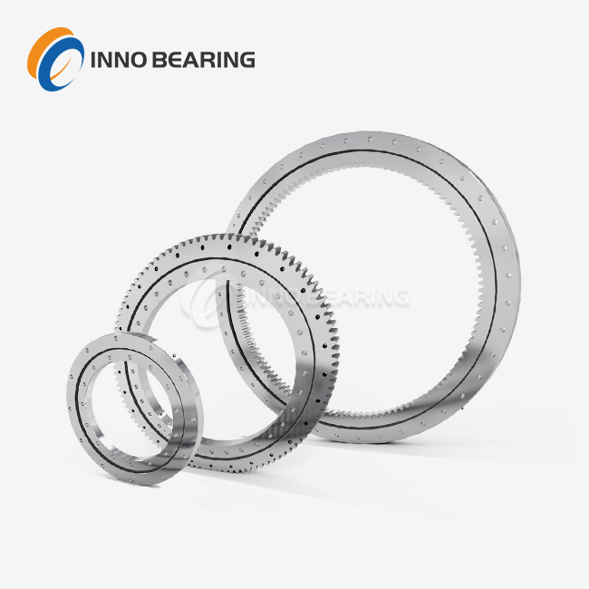
Where duty permits, the four-point contact ball slewing bearing family remains the most economical starting point — one row of balls in a Gothic arch raceway reacting axial load in both directions, radial load and tilting moment at once. Step away from it only when something specific forces you to.
6. Choose the type
Type selection is a trade between capacity, rigidity, section height and cost. The table below summarises the mainstream families; all of them are available with internal, external or no gear and with a range of sealing and lubrication options.
| Type | Moment capacity | Rigidity | Section height | Cost | Typical duty |
|---|---|---|---|---|---|
| Single-row four-point contact ball | Medium | Medium | Compact | Low–medium | General cranes, small excavators, aerial platforms, solar trackers |
| Double-row ball | Medium–high | Medium–high | Moderate | Medium | Mobile cranes, wind turbine yaw, larger overhung loads |
| Cross roller | High | Very high | Very compact | Medium–high | Indexing tables, robotics, machine tools, mid-size construction equipment |
| Three-row roller | Very high | Very high | Large | High | Heavy lattice boom cranes, mining shovels, tunnel boring machines, port machinery |
| Ball and roller combination | High | High | Moderate–large | Medium–high | Specific duty where an optimised split between ball and roller rows pays off |
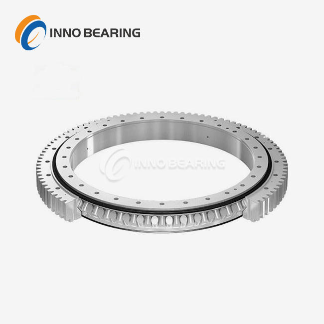
A useful rule of thumb: start with the four-point contact ball family because it is the most economical per unit of capacity and covers the majority of general duties. Step up to cross roller when you need stiffness or capacity in a restricted envelope, and to heavy-duty three-row roller when capacity is genuinely the governing requirement and the structure can carry the larger, heavier ring.
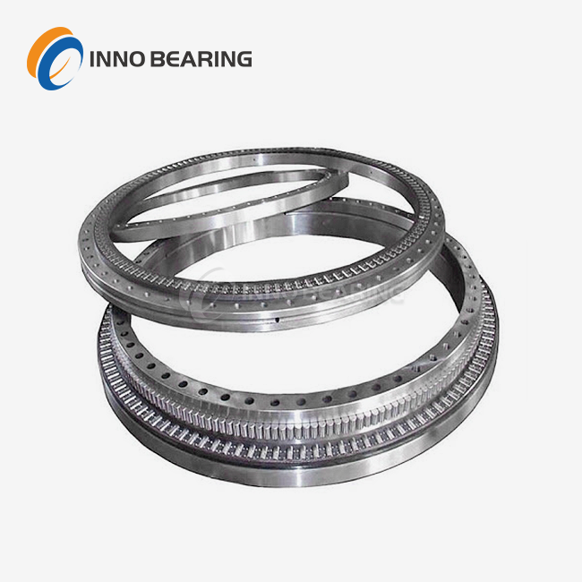
7. Specify the gear
If the ring is to be driven, three choices have to be made and they interact with the drive design, not just with the bearing.
| Configuration | Advantages | Trade-offs | Choose when |
|---|---|---|---|
| External gear | Teeth accessible for inspection and re-lubrication; drive mounting straightforward | Larger envelope; teeth exposed to damage and weather | Default choice where the layout allows it |
| Internal gear | Most compact arrangement; tooth mesh protected from contamination | Inspection and service access harder | Envelope is tight or the environment is very dirty |
| No gear | Simplest and cheapest ring; full design freedom for the drive | Drive solution must be found elsewhere | Friction drive, external slewing drive unit, or unpowered rotation |
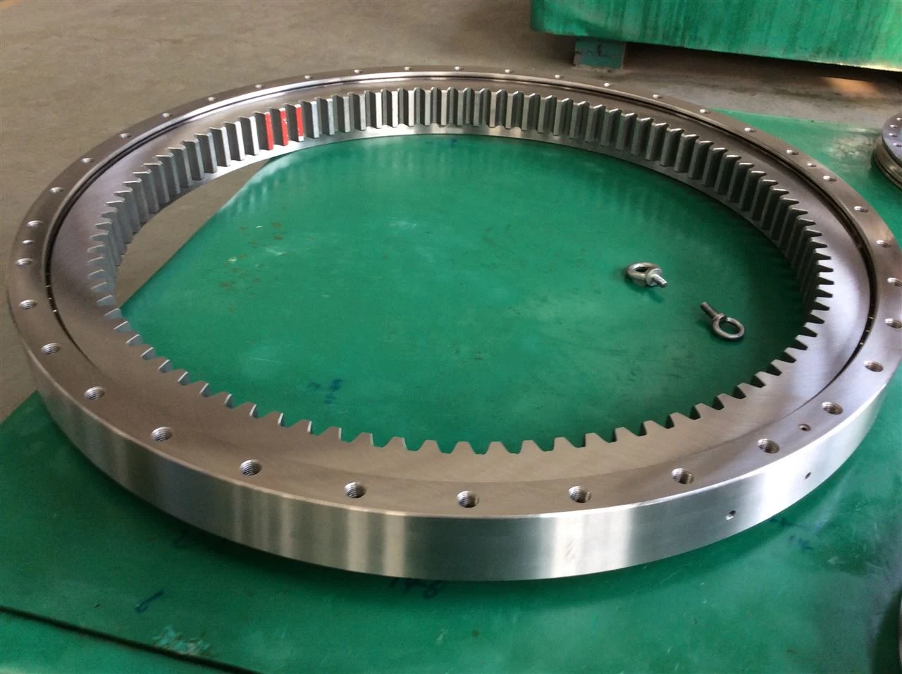
Two specification points consistently separate rings that last from rings that wear their teeth out early. First, insist on induction-hardened tooth flanks rather than through-normalised material — a hardened flank survives far more of the inevitable overload cycles. Second, specify the tooth accuracy grade rather than leaving it to chance; the required grade follows from your backlash requirement and the drive torque, and it is much cheaper to specify correctly up front than to discover the problem during commissioning.
8. The interface — where most failures actually happen
A slewing bearing is usually the most precisely made component in the joint. It is also usually the softest. The failures that reach our desk most often have nothing to do with the raceway:
- Mounting face not flat enough. The ring is designed to run flat. Bolted to a surface out of tolerance, it takes the shape of that surface and the load concentrates in a fraction of the intended contact area.
- Bolts not preloaded to specification. Use high-strength bolts at the grade the supplier specified — typically 10.9 or 12.9 for this duty — torqued in a cross pattern in several passes. Spring washers have no place in a properly preloaded joint.
- Supporting structure softer than the ring. If the pedestal deflects more than the ring, the load path moves to the ring edge and premature failure follows. The support structure should be verified for stiffness, not just strength.
- Bolts re-torqued once and then forgotten. Check bolt preload after the first hours of service and at defined intervals thereafter, particularly on shock-loaded machines.
Ask your supplier for the required mounting-face flatness tolerance and the bolt grade, quantity and torque figure for the specific ring being supplied. On large-diameter rings this data is size-dependent and should never be assumed.
9. Seals, lubrication and backlash
Sealing and lubrication decisions are made at selection time because they are built into the ring, not added afterwards. Standard nitrile (NBR) seals suit most industrial duty; where the ring sees sustained high temperature or aggressive chemicals, fluoroelastomer (FKM) is worth the premium. Marine and wash-down environments justify additional external shielding.
Plan relubrication rather than hoping for it. A ring should be greased to purge contaminants shortly after first going into service, then at an interval set by duty rather than by calendar habit — a ring indexing continuously in a hot steel plant and one rotating a few degrees twice a day on a solar tracker need very different regimes.
Finally, agree the required backlash or preload with the supplier at quotation stage. Tight-backlash applications are quoted differently from standard ones, and the difference is far cheaper to buy up front.
10. Checklist — the mistakes worth avoiding
- Taking the independent maximum of each load instead of the simultaneous worst case
- Using the outside diameter instead of the raceway centre diameter in Q = 2.55 M / D
- Specifying to L10 fatigue life when static capacity governs
- Selecting on the machine’s dead weight and treating the tilting moment as a refinement
- Accepting a quotation without the supplier’s load curve marked with your own loads
- Treating the gear accuracy grade and tooth hardening as optional
- Checking the ring but never checking the flatness, stiffness and bolt preload of what it bolts to
- Failing to agree relubrication intervals and backlash figure before ordering
- Ordering the ring and the drive separately, then finding at commissioning that the pinion does not match the ring
On that last point: where the whole rotation package is being replaced rather than just the ring, an integrated slew drive bearing removes the gear-matching risk entirely, because the pinion, housing and ring are supplied and tested as one assembly.
11. What to send when you ask for a quotation
Slew rings are made to order more often than people expect, and the quotation is only as good as the input. Send these and you will get a priced, engineered answer rather than a catalogue guess:
- Simultaneous worst-case Fa, Fr and M, stated with the units and the duty position they correspond to
- Duty cycle — operating hours per year, cycles per hour, rotation angle and speed, any shock loading
- Mounting interface: available outside diameter, bolt circle, height limit, number and grade of bolts
- Gear: internal, external or none; required drive torque or pinion specification
- Ambient and process temperature at the bearing location, plus any contamination, salt or wash-down exposure
- Sealing and lubrication preferences, corrosion protection requirements
- Space constraints that would force a compact cross roller design rather than a larger ball ring
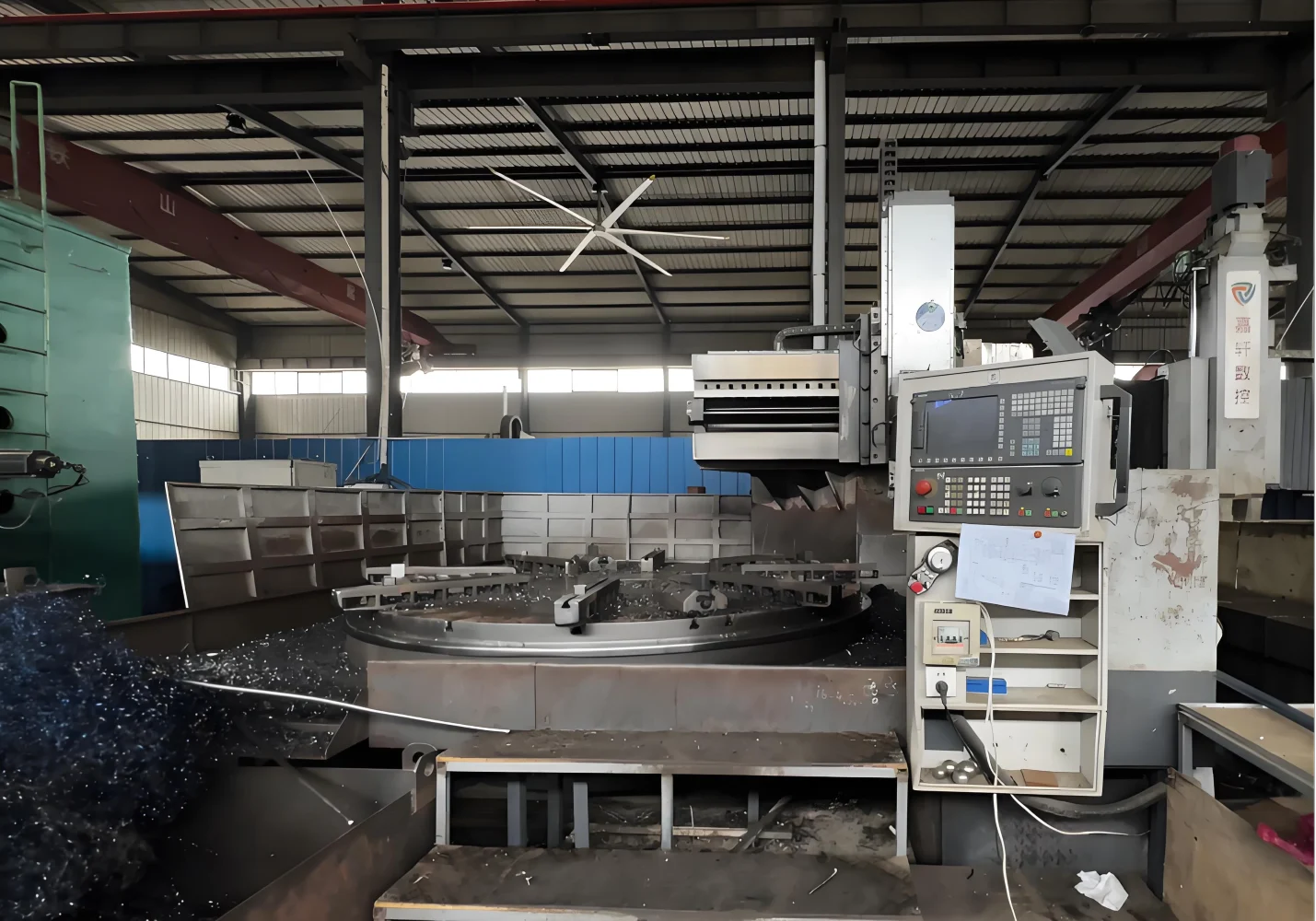
INNO BEARING manufactures slew rings from 200 mm to over 5 000 mm, with vertical lathes in-house to 5 m and full heat treatment control on the raceway and gear. Send the figures above to [email protected] and we will return a size recommendation with the load curve marked up and a quotation.
12. Frequently asked questions
Related reading
The same load-first approach applies on the mill side: Rolling Mill Bearing Selection: Types & Sizing covers four-row cylindrical versus four-row tapered roll neck bearings, L10 sizing where it does apply, and the clearance and fit decisions that follow. For the machinery fitted with our larger rings, the excavator slewing bearing, tower crane slewing ring and large diameter slewing bearings ranges cover most of the duty classes discussed above.