
Maintenance of Large Four-Row Tapered Roller Bearings: A Field Guide for Rolling Mills
Large four-row tapered roller bearings carry the heaviest loads in a rolling mill. They sit on the work rolls and back-up rolls of hot strip mills, plate mills and cold mills, absorbing radial rolling forces and axial thrust at low speed and extreme load. Because a single set can be several metres in circumference and worth tens of thousands of dollars, correct maintenance of large four-row tapered roller bearings is one of the highest-return activities in any mill maintenance programme.
This guide is written for mill maintenance engineers, roll shop supervisors and reliability teams. It covers the failure modes you actually see, how much grease to add and when, how to handle matched bearing components, how to check axial internal clearance, and what to measure before a bearing goes from serviceable to scrap.
1. Where these bearings work — and why maintenance decides their life
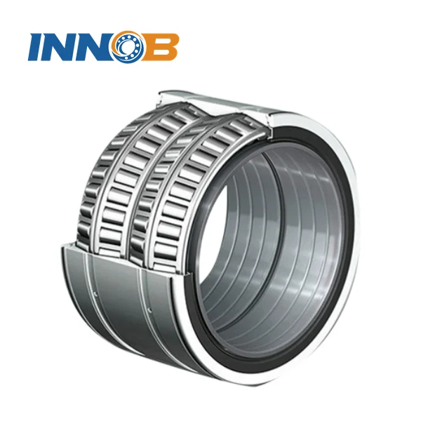
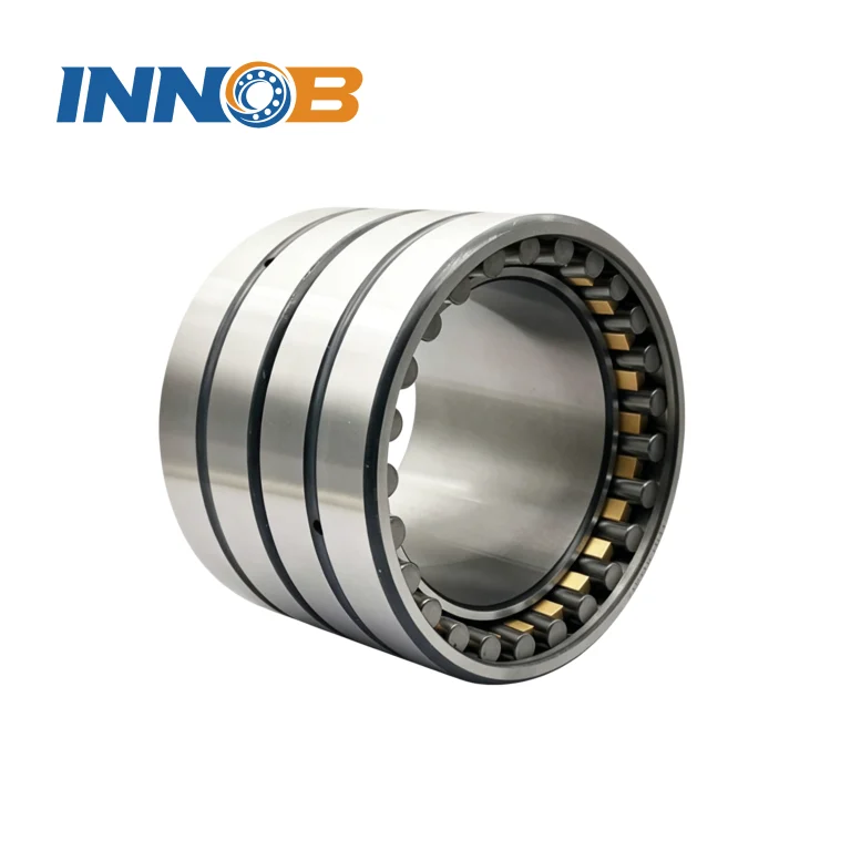
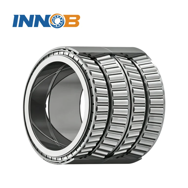
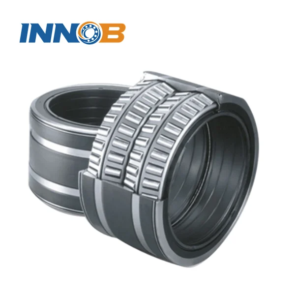
A four-row tapered roller bearing typically consists of two double-row inner rings, two single outer rings and one double outer ring, plus inner and outer spacers (shims), rollers and cages. Some designs eliminate the spacer rings entirely, which reduces component count and makes fitting more repeatable.
The classic arrangement mounts the bearing directly on the roll neck with a loose (clearance) fit so the inner ring can creep slightly and let the load zone move. In service the bearing is surrounded by:
- rolling forces that can exceed the static load rating during cobble events;
- cooling water, scale and oxide particles;
- temperatures from the roll body conducted straight into the inner rings;
- very low rotational speeds, which means the lubricant film is thin and boundary conditions are common.
Under these conditions, maintenance quality matters more than bearing quality. Field experience repeatedly shows bearing sets failing long before their rating life because of water ingress, wrong relubrication quantities, incorrect axial clearance, or reusing components out of their matched order.
2. The failure modes you will actually meet
Classifying damage correctly is the first step of root-cause work. The industry standard reference is ISO 15243, which groups rolling bearing failure into six classes: fatigue, wear, corrosion, electrical erosion, plastic deformation, and cracking / fracture. In a mill you will mostly see the following patterns:
| Symptom found at inspection | ISO 15243 class | Usual root cause | Corrective action |
|---|---|---|---|
| Spalling at one edge of the raceway | Fatigue | Axial clearance too small (preload) or misalignment / roll neck deflection | Re-measure and correct axial clearance; check roll neck geometry and chock fit |
| Frosting, mirror finish, sharp wear particles | Wear — abrasive | Scale or grinding dust entering the chock; damaged seals | Replace seals, flush housings, improve filtration of the lubrication system |
| Grey-black staining, etching, corrosion pits | Corrosion — moisture | Cooling water ingress, blocked drain slots, condensation during storage | Clear drain slots at the 6 o'clock position, verify seal lips, review preservation method |
| Roller ends and guide flange heavily scored | Wear — adhesive | Starved lubrication, wrong grease consistency, over-long relubrication interval | Shorten interval, recalculate grease quantity, check pump and delivery lines |
| Cage pockets worn, cage broken | Fracture / Fatigue | Excessive axial load, cocking during mounting, mismatch of components | Review thrust duty and mounting procedure; never mix components from different sets |
| Localised deep indentation along raceway | Plastic deformation | Impact during handling, or static overload / shock load in service | Improve lifting and storage practice; review roll force limits |
3. Lubrication: getting the quantity and interval right
Over-lubrication is as damaging as starvation. Too much grease churns, heats, oxidises the thickener and, at grease-gun pressures that can reach thousands of psi, can even blow out seal lips. Too little grease leaves the tapered contacts in boundary lubrication.
Relubrication quantity
The widely used bearing-manufacturer formula for the amount added at each relubrication event is:
Gp = 0.005 × D × T
- Gp — grease to be added, in grams
- D — bearing outside diameter, mm
- T — total bearing width, mm (use T for tapered roller bearings, not B)
When grease is fed through lubrication holes in the centre of the inner or outer ring instead of from the side of the bearing, the recommended quantity drops to Gp = 0.002 × D × T.
Worked example. A back-up roll bearing with OD 900 mm and total width 620 mm:
Gp = 0.005 × 900 × 620 = 2 790 g ≈ 2.8 kg per relubrication cycle from the side of the bearing.
Do not stop at grams. Calibrate the actual grease gun: measure how many grams one stroke delivers with that specific grease, convert the result into pump strokes, and write the stroke count on the job card. "Add roughly some grease" is how fleets develop both over- and under-lubricated bearings on the same stand.
Intervals and initial fill
- Initial fill: as a rule of thumb for standard-speed duties, 30–50 % of the free volume in the housing; for very low-speed applications a higher fill of 70–100 % may be used, always with a relief path for excess grease.
- Sealed executions: some four-row tapered roller bearing designs are supplied completely sealed with no relubrication facility. Those are filled with a high-quality grease at mounting and typically run around 1 000 to 1 500 hours before the set is pulled from the chock, washed, inspected, re-greased and refitted.
- Fully automatic systems: oil-air lubrication meters a very small quantity continuously and roughly eliminates over-lubrication risk at high rolling speeds; circulating oil and oil-mist remain viable for open designs.
- Consistency: never mix greases with incompatible thickeners. If the product changes, purge thoroughly and confirm compatibility first.
4. Mounting and dismounting: matched components and load-zone rotation
Four-row tapered roller bearings are supplied as a matched set. All components carry the same serial number and a position letter, and components of the same size from different bearings are not interchangeable. Follow the assembly order printed in the mounting sheet that ships with the bearing — if row order is wrong, the load distribution is wrong and the bearing will fail early.
Rotating the load zone
The side faces of the outer rings are divided into four load zones marked I to IV. Recommended practice:
- On first mounting, position zone I in the direction of the load.
- At each planned reconditioning campaign, rotate the outer rings so the next zone takes the load (turn through 90°).
- After four campaigns the bearing returns to zone I, by which point fatigue damage usually dominates and the set is a replacement candidate.
This single habit typically multiplies service life, because it spreads fatigue over the full circumference instead of concentrating it in one sector.
Axial location of the inner rings
The inner rings must not be axially clamped hard against their abutments. A total axial clearance of roughly 0.4 to 1.3 mm between the inner rings and the abutments is the usual requirement, which allows the inner ring to creep and equalise load. Modern narrowly-toleranced designs (± 0.25 mm on width) deliver this automatically when the associated chock dimensions are machined to specification, removing the need for adjustment by lock nut.
Roll neck requirements
- Roll neck journal surface hardness: about 45 HSh (≈ 34 HRC) minimum.
- Axial abutments for the inner rings: about 60 HSh (≈ 45 HRC) minimum.
- Fits: inner ring to roll neck is normally a loose / clearance fit; outer ring to housing bore commonly around G7 depending on diameter.
5. Measuring and correcting axial internal clearance
Axial internal clearance is the number that decides whether a four-row tapered roller bearing runs free or runs hot. Clearance is set by the width of the inner and outer spacers, not by the lock nut.
Field method
- Wash and dry every component after inspection. Never measure a dirty bearing.
- Lay the bearing on a flat surface plate or level table. Before measurement, make the end face of the lower inner ring parallel to the plate.
- Place a loading block or weight on the upper outer ring so rollers and raceways are in uniform contact, and rotate rings and rollers several times to seat everything.
- Measure with a feeler gauge or dial indicator at four equally spaced points around the circumference and take the mean value as the actual clearance.
- Correct by re-grinding or exchanging the inner spacer / outer spacer. Do not shim randomly — successive measurements at four points tell you whether you have a sizing problem or a parallelism problem.
A conversion commonly quoted in metallurgical bearing literature relates required axial clearance Ga to the bearing radial clearance Gr and the axial load factor e: Ga ≈ 1.5 × Gr / e. Because e varies by design and duty, always confirm the target against the manufacturer's tables for the specific bearing type before setting spacers.
When damage exceeds roughly one quarter of the raceway width, repair is no longer economical — replace the set rather than re-grind.
6. Condition monitoring: what to trend, and where the alarm lies
| Parameter | How to measure | Practical trigger to investigate |
|---|---|---|
| Operating temperature | Contact probe or fixed sensor on the outer ring / chock | Trend first: a rise of about 15–20 K above the steady-state baseline is more meaningful than an absolute number. Many mills alarm around 80–90 °C at the chock — always against your own spec. |
| Vibration | Route-based collector or online accelerometer | Rising overall levels plus bearing defect frequencies, evaluated against ISO vibration severity criteria for large machines |
| Lubricant condition | Grease sample from the purge; wear particle / ferrographic analysis | Water above trace levels, hard particles, or heavy iron content |
| Ultrasound | Handheld ultrasonic instrument | Film condition change after relubrication; useful for confirming effective delivery within the first hours |
| Chock condition | Dimensional check at every campaign | Bore out of round / cylindricity out of tolerance, blocked lubrication ducts, worn seal seats |
7. Sealing, water and contamination control
Water is the enemy of every mill bearing. Practical measures:
- Keep drain slots open and located at the 6 o'clock position so water entering past external seals can escape instead of pooling.
- Clean lubrication and ventilation ducts with compressed air and solvent at every chock rebuild; use a magnetic rod to pull residual swarf from drillings.
- Check seal lips, seal seats and chock covers every campaign; replace rather than straighten a deformed lip.
- Use filtered, dry air when blowing down the area, and keep bearings wrapped until the moment of mounting.
8. Handling, storage and preservation
- Store bearings horizontally in their original packaging, in a dry, vibration-free room with stable temperature.
- Do not unwrap until immediately before mounting.
- Lift with the correct slings and spreader beams; never let a ring take an impact load.
- Adopt first-in / first-out stock rotation and watch grease shelf life in the store, not only in service.
- Record every bearing's installation position, campaign dates, load zone used, and measured clearances. Without this history you cannot trend anything.
9. Maintenance schedule you can hand to the crew
| Frequency | Task |
|---|---|
| Per shift / daily | Check chock temperature trend, listen for abnormal noise, confirm automatic lubrication system pressure and reservoir level |
| Weekly | Relubricate to the calculated quantity (if applicable), note grease consumption, inspect external seals and drain slots |
| Monthly | Vibration and temperature route carried out; ultrasonic check after relubrication; review trend charts |
| Each roll change / campaign | Pull and open the set; wash and inspect; measure axial clearance at four points; check corresponding chock and roll neck dimensions; replace seals; rotate load zone 90°; re-assemble in the marked order with fresh grease |
| Annually | Review the full failure and repair history; re-derive relubrication quantities and intervals from actual operating temperature and contamination levels |
10. Troubleshooting quick reference
| What you observe | Probable cause | What to do first |
|---|---|---|
| Temperature climbs right after relubrication | Over-greasing and churning | Stop adding grease, open relief path, allow excess to purge, re-check the calculated quantity |
| Temperature high and steady with dry, crusty grease | Thickener hardened from heat; starvation despite a full housing | Purge thoroughly, clean out hardened deposits, verify grease specification |
| Grease leaking outside the chock | Seal lip damaged or over-pressurised | Inspect and replace seals; check relief ports are not plugged |
| Axial movement of the roll is excessive | Clearance too large or abutments worn | Re-measure axial clearance, re-size spacers, check roll neck abutment hardness and wear |
| Spalling confined to one zone of the raceway | Load zone not rotated, or clearance too tight | Rotate load zone at next campaign and correct clearance |
| Rapid repeat failures on the same stand | Chock bore geometry, misalignment or roll neck deflection | Measure chock bore and roll neck; check stand alignment rather than blaming the bearing |
11. Frequently asked questions
How often should large four-row tapered roller bearings be relubricated?
Base the starting interval on the bearing size, speed and operating temperature from the manufacturer's tables, then adjust using your own temperature trend and grease condition. Low-speed mill bearings often run on weekly schedules, but contamination levels and seal condition matter more than calendar time.
How much grease does a four-row tapered roller bearing need?
For replenishment from the side of the bearing, Gp = 0.005 × D × T grams, where D is outside diameter and T the total width in millimetres. Through lubrication holes in a ring, use Gp = 0.002 × D × T. Convert grams into calibrated grease-gun strokes for the crew.
Can components from two identical four-row tapered roller bearings be mixed?
No. Components of one bearing are matched and serialized and are not interchangeable with those of another bearing of the same size. Always assemble in the documented order, otherwise load distribution and clearance will be wrong.
Why should the outer rings be rotated 90° at every campaign?
Rotating to the next load zone spreads fatigue over the full circumference rather than concentrating it in one sector, which measurably extends total service life.
Should the inner rings be clamped tightly on the roll neck?
No. Leave roughly 0.4 to 1.3 mm total axial clearance between the inner rings and their abutments so the inner ring can creep and no unintended preload develops.
When should a bearing set be scrapped instead of repaired?
As a common field rule, when spalling exceeds about a quarter of the raceway width, or when cage fracture, cracking or deep corrosion pitting is present, replacement is safer and cheaper than re-grinding.
What seals the deal on bearing life: bearing quality or maintenance?
Maintenance. Starved lubrication, water ingress, incorrect axial clearance and mixing matched components will destroy a premium bearing just as fast as a budget one.
Need the right bearing for the job?
INNO BEARING supplies large four-row tapered roller bearings, including inch-series executions, for hot strip mills, plate mills, cold mills and section mills, together with cup-and-cone matching, spacer sizing and roll-neck fit recommendations. Send us your existing designation or roll neck drawing and we will confirm interchangeability, clearance class and delivery.
Explore the range: Four-row Tapered Roller Bearings, Four Row Tapered Roller Bearing (metric), Inch Series Four Row Tapered Roller Bearings, or the full Tapered Roller Bearings catalogue. Technical questions: [email protected].