
Rolling Mill Bearing Selection: How to Specify the Right Roll Neck Bearing for Every Stand
Rolling mill bearing selection is not a catalogue lookup. A single roll neck bearing set on a hot strip mill can be two metres in diameter and worth more than a mid-size car, and an unplanned chock failure costs far more in lost production than the bearing itself. Yet the same three mistakes account for most premature failures: choosing the type by habit instead of by load case, sizing on boundary dimensions instead of load rating, and specifying the bearing without specifying the clearance, fit and lubrication that go with it.
This guide walks through the decision in the order a mill engineer actually makes it — stand by stand, then type, then size, then the details that decide whether the bearing reaches its rating life. It is written for maintenance and reliability engineers, roll shop supervisors and anyone specifying replacement bearings for a mill.
1. Start with the stand, not the catalogue
Before you compare bearing types, write down what the bearing actually has to survive. Every number below moves the specification:
- Radial load — the roll separating force, split between the two chocks, plus any overload during cobble or threading events.
- Axial load — often small on an ideal stand, but large on reversing mills, on stands with worn guides, and whenever the strip runs off centre.
- Speed — roll neck rpm and the surface speed of the strip. High-speed stands push you towards cylindrical rollers and oil systems; slow, heavily loaded stands leave both options open.
- Temperature — conducted heat from the roll body, plus ambient and cooling conditions.
- Contamination — cooling water, oxide scale, and, in cold mills, rolling emulsion.
- Envelope — roll neck diameter and the radial space available in the chock. This is usually fixed by the mill design and is the hardest constraint to escape.
- Campaign length and target life — how long the set must run between roll changes, and what L10h the plant expects.
- Mounting practice — how often the set comes off, and whether the crew can handle matched, serialised components.
What each mill stand typically uses
| Mill / position | Usual bearing arrangement | Why |
|---|---|---|
| Hot strip mill — work rolls | Four-row tapered roller bearing, or four-row cylindrical + thrust | Frequent reversing and uncertain axial impact; tapered handles both load directions in one envelope |
| Hot strip mill — back-up rolls | Four-row cylindrical roller bearing + separate thrust bearing | Almost pure radial load, highest radial capacity per envelope, separable for fast roll changes |
| Plate / heavy plate mill | Four-row cylindrical + thrust roller bearing | Very high radial load at low speed; thrust roller bearings take heavy axial load with small axial clearance |
| Cold strip mill (4-high / 6-high) | Four-row cylindrical + angular contact thrust ball bearing | High rolling speed; angular contact gives tight axial guidance and high limiting speed |
| Foil and thin-gauge mills | Four-row cylindrical + angular contact thrust | Speed and axial precision dominate over peak capacity |
| Wire rod and bar mills | Four-row cylindrical roller bearing | Highest speed in the plant; cylindrical gives the limiting-speed margin |
| Reversing / blooming / section mills | Four-row tapered roller bearing | Bi-directional axial shock on every reversal, compact chock, no extra thrust housing needed |
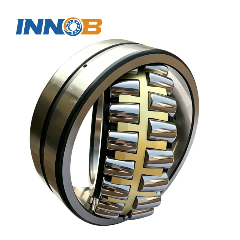
| Legacy installations | Two spherical roller bearings side by side | Historical practice, limited to roughly 600 rpm; short life and heavy roll neck wear — replace during modernisation |
2. The type decision: four-row cylindrical or four-row tapered?
This is the single most consequential choice in rolling mill bearing selection, and it comes down to one question: does this position carry meaningful axial load?
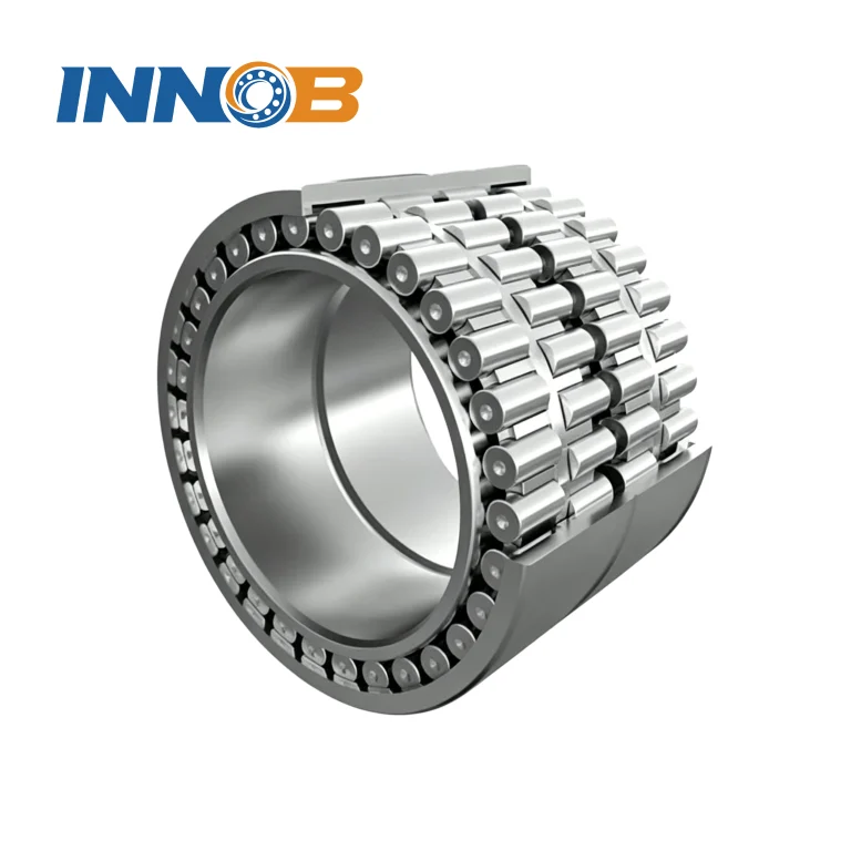
Four-row cylindrical roller bearing + thrust bearing
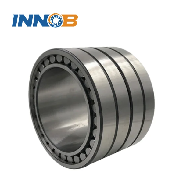
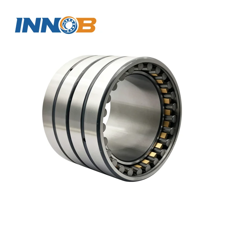
Cylindrical rollers run on line contact, which gives the highest radial load capacity of any mill bearing geometry for a given envelope, and the lowest sectional height — valuable when the chock has limited radial space. The inner and outer rings are separable, so the roll can be pulled and the bearing inspected or swapped without destroying anything. Its limit is axial: a four-row cylindrical bearing carries essentially no axial load, so it must be paired with a dedicated thrust bearing.
- Strengths: highest radial capacity, high limiting speed, separable rings, easy mounting and roll change, absorbs axial float from thermal growth.
- Limits: needs a separate thrust bearing and the housing space for it; inner ring is normally an interference fit on the roll neck, so mounting takes more care.
- Thrust pairing: heavy load at low speed → thrust roller bearing; high speed → angular contact thrust ball bearing, which also controls axial play tightly.
Four-row tapered roller bearing
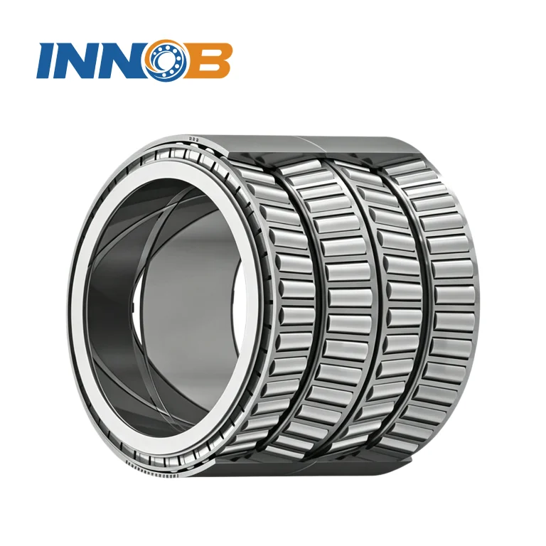
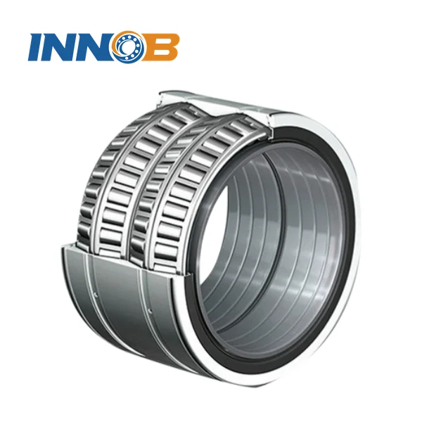
Tapered rollers carry combined radial and axial load in one unit, in both axial directions, so no separate thrust bearing and no extra housing length are needed. Internal clearance is set by spacer widths, which lets you tune the bearing to the duty. The inner ring runs with a loose fit on the roll neck, which makes mounting and dismounting fast — and also allows the load zone to be rotated between campaigns, spreading fatigue around the circumference.
- Strengths: combined radial + axial capacity, compact and integrated chock, adjustable internal clearance, tolerant of axial shock, excellent accuracy retention, available in X and O arrangements.
- Limits: lower limiting speed than cylindrical; the loose inner-ring fit can creep, so inner ring bores are often machined with spiral oil grooves; components are matched and serialised and must never be mixed between sets.
Side-by-side comparison
| Criterion | Four-row cylindrical + thrust | Four-row tapered |
|---|---|---|
| Radial capacity in a given envelope | Highest | Very high |
| Axial capacity | None — needs a separate thrust bearing | High, both directions, built in |
| Limiting speed | Higher | Lower |
| Roll neck fit | Interference fit on inner ring | Loose / clearance fit, inner ring may creep |
| Mounting and roll change | Separable rings, fast | Fast, but matched components must stay in order |
| Axial guidance of the roll | Depends on the thrust bearing chosen | Inherent, adjustable |
| Space required | More (bearing + thrust) | Less, more compact chock |
| Typical position | Back-up rolls, cold mills, wire rod, foil | Hot mill work rolls, reversing and section mills |
Rule of thumb. If the axial load is a small fraction of the radial load and speed is high, go cylindrical plus thrust. If the stand sees real axial thrust, frequent reversal or shock, or the chock has no room for a thrust bearing, go tapered.
3. Sizing: L10 life, and the static check nobody does
Once the type is chosen, size it by rating life, not by bore diameter. The ISO 281 basic rating life for roller bearings is:
L10 = (C / P)10/3 million revolutions
L10h = (106 / 60 n) × (C / P)10/3 hours
- C — basic dynamic load rating from the bearing table, in kN
- P — equivalent dynamic load, P = X · Fr + Y · Fa. For pure radial load, X = 1 and Y = 0, so P = Fr
- n — rotational speed, rpm
- The exponent is 10/3 for roller bearings and 3 for ball bearings
The exponent is the whole story: doubling the load cuts roller bearing life by roughly a factor of ten. A modest overload is far more damaging than it looks, and stepping up one bearing size is far more effective than it looks.
Worked example
A four-high cold mill work roll position. Per chock: Fr = 3 200 kN, n = 300 rpm, target L10h = 20 000 h.
- Required life in revolutions: L10 = 20 000 × 60 × 300 / 106 = 360 million revolutions.
- Required load ratio: C/P = 3603/10 ≈ 5.85.
- Required rating: C = 5.85 × 3 200 ≈ 18 700 kN.
- Candidate bearing with C = 19 500 kN: L10 = (19 500 / 3 200)10/3 = 6.0910/3 ≈ 413 million revolutions → L10h = 413 × 106 / (60 × 300) ≈ 22 900 h. Meets target with margin.
- Sensitivity check: a sustained 20 % overload gives L10h ≈ 22 900 / 1.210/3 ≈ 12 500 h — half the life from one fifth more load.
The static check
Mill bearings also see stationary or slowly oscillating load with heavy shock — threading, cobble events, roll stack preload. Check the static safety factor:
s0 = C0 / P0
Target s0 ≥ 1.5 for normal duty and ≥ 3 where shock or impact is routine. Exceeding C0 permanently brinells the raceways, and no amount of good lubrication undoes it.
4. Fit, clearance and roll neck geometry
Three details decide whether a correctly sized bearing survives. All three are specified with the bearing, not after it.
Fit
- Cylindrical: inner ring normally an interference fit on the roll neck; outer ring located in the chock bore.
- Tapered: inner ring a loose / clearance fit so it can creep and let the load zone move. Because that fit can creep, inner ring bores are commonly machined with spiral oil grooves to hold lubricant and keep wear debris away from the raceways.
- Tapered inner ring axial clearance: do not clamp the inner rings hard against their abutments. Leave roughly 0.4 to 1.3 mm total axial clearance so the ring can creep and no unintended preload develops.
Clearance
Internal clearance is the most under-specified parameter in mill bearing orders. ISO 5753 defines groups C2, CN, C3, C4 and C5 in increasing clearance. Large mill bearings are usually supplied in non-standard, application-specific clearance groups, and for four-row tapered sets the axial clearance is set by grinding or exchanging the inner and outer spacers — not by the lock nut.
Measure the assembled axial clearance at four equally spaced points around the circumference and take the mean. Four points tell you whether you have a sizing problem or a parallelism problem; a single reading tells you neither.
Roll neck and chock condition
- Roll neck journal surface hardness: about 45 HSh (≈ 34 HRC) minimum.
- Axial abutments for the inner rings: about 60 HSh (≈ 45 HRC) minimum.
- Check chock bore roundness and cylindricity, and confirm lubrication ducts are clear, at every roll change.
- Tolerance class: Normal (P0) for general duty; P5 or better for high-precision cold mills and foil mills.
5. Material, heat treatment and cage
| Choice | Where it applies | Why |
|---|---|---|
| Case-carburised steel (e.g. 20Cr2Ni4A / 18CrNiMo7-6 type) | Large mill bearings, heavy shock duty | Hard, fatigue-resistant case with a tough, crack-resistant core. Survives impact that would fracture a through-hardened ring |
| Through-hardened high-carbon chromium steel (GCr15 / 100Cr6 / 52100) | Smaller sizes, steady load | Uniform 58–64 HRC, proven fatigue performance, lower cost |
| Vacuum-degassed, low-inclusion steel | Any critical position | Fewer non-metallic inclusions delays subsurface-initiated spalling |
| Dimensional stabilisation S0 (150 °C) / S1 (200 °C) / S2 (250 °C) | Hot mills and any bearing running hot | Standard steel is only stable to about 120 °C; above that the rings change dimension in service |
| Machined brass cage (finger or window type) or hardened steel cage | Most mill bearings | Strength at high load and shock, resistant to the water and heat a mill delivers |
6. Choosing the lubrication method
Type of lubricant is a selection decision, not a maintenance afterthought — it sets the achievable speed, the heat removal and the contamination tolerance.
| Method | Best for | Watch out for |
|---|---|---|
| Grease | Most mill positions; simple, seals well, low infrastructure cost | Over-greasing churns and heats; measure the quantity. Replenishment from the side: Gp = 0.005 × D × T grams |
| Circulating oil | High speed, high temperature, need to flush debris and remove heat | System complexity, filtration and leakage management |
| Oil mist | Continuous supply to multiple points, clean delivery | Mist generation, environmental and housekeeping controls |
| Oil-air (minimum quantity) | High-speed finishing stands | Meters a very small quantity continuously and largely removes the over-lubrication risk, but needs a correctly commissioned system |
Whichever you choose: set the initial fill (a common rule is 30–50 % of free housing volume, higher for very low speed but always with a relief path), define the interval from operating temperature and contamination rather than from the calendar, and never mix greases with incompatible thickeners.
For the full lubrication quantities, load-zone rotation and axial clearance procedure on four-row tapered sets, see our companion guide: Maintenance of Large Four-Row Tapered Roller Bearings.
7. Sealing and contamination control
Water and scale destroy more mill bearings than load does. Specify the sealing as part of the bearing package:
- Combine a labyrinth with lip seals — the labyrinth keeps bulk water out, the lip holds grease in.
- Keep drain slots open and at the 6 o’clock position so water that gets past the outer seal can escape instead of pooling in the chock.
- Check seal seats and chock covers at every campaign; replace a deformed lip rather than straightening it.
- Keep bearings wrapped until the moment of mounting, and use clean, dry air when blowing down the area.
8. Selection checklist
| Step | Confirm | Common trap |
|---|---|---|
| 1. Duty | Radial load, axial load, speed, temperature, contamination, envelope | Sizing on bore diameter alone because “it must match the old one” |
| 2. Type | Cylindrical + thrust, or tapered | Specifying cylindrical with no thrust bearing on a reversing stand |
| 3. Size | C from L10h target; s0 static check | Ignoring shock load — the 10/3 exponent punishes it hard |
| 4. Fit | Interference (cylindrical) or loose with spiral grooves (tapered) | Clamping tapered inner rings hard and creating preload |
| 5. Clearance | Clearance group, spacer widths, four-point measurement | Defaulting to CN because it is the catalogue standard |
| 6. Material | Case-carburised vs through-hardened; stabilisation class | Standard steel on a hot stand that runs above 120 °C |
| 7. Lubrication | Method, initial fill, interval, quantity in grams per cycle | “Add some grease” — the fastest route to both over- and under-lubrication |
| 8. Sealing | Labyrinth + lip, drain slots, seal seat condition | Fitting a new bearing into a chock with blocked drains |
| 9. Interchangeability | Boundary dimensions, designation, matched set integrity | Mixing components from two sets of the same size |
| 10. Records | Installation position, campaign dates, clearances measured, load zone used | No history — which means no trending, and no way to prove anything |
9. Mistakes we see repeatedly
| Mistake | What happens | Do this instead |
|---|---|---|
| Specifying by bore and OD only | Bearing fits but dies early; identical dimensions, very different C | Specify designation and required C |
| Four-row cylindrical with no thrust bearing | Axial load goes where it was never meant to go | Always pair cylindrical with the thrust bearing the duty needs |
| Tapered set assembled in the wrong row order | Wrong load distribution, early failure | Follow the mounting sheet; matched components stay together |
| Mixing components from two sets | Clearance and load distribution wrong | Never mix — serial numbers and position letters exist for a reason |
| Standard clearance on a hot stand | Bearing seizes as it expands | Specify the clearance group for the operating temperature |
| Seals and drains ignored | Water sits in the chock, corrosion pitting follows | Seal and drain are part of the bearing specification |
| Choosing on unit price | Cheapest bearing costs more per rolling hour | Compare cost per 1 000 rolling hours including downtime |
| No installation records | No trend, no root cause, repeat failures | Log every set: position, dates, clearances, load zone |
10. Frequently asked questions
Which is better for a rolling mill — four-row cylindrical or four-row tapered roller bearings?
Neither is universally better. Four-row cylindrical gives the highest radial capacity and limiting speed but carries almost no axial load, so it needs a separate thrust bearing — standard on back-up rolls, cold mills and wire rod mills. Four-row tapered carries radial and axial load together in a compact chock, which suits hot mill work rolls and reversing or section mills with real axial shock.
How do I calculate the required bearing size for a roll neck?
Use L10 = (C / P)10/3 for roller bearings, convert to hours with L10h = (106 / 60 n) × (C / P)10/3, and solve backwards for the C you need. Then check the static safety factor s0 = C0 / P0, targeting at least 1.5 and 3 or more under shock.
Why does a small overload shorten mill bearing life so much?
Because life scales with the 10/3 power of load. A 20 % sustained overload roughly halves life; doubling the load reduces it by about a factor of ten. This is why the shock and cobble duty matters as much as the nominal rolling force.
Can I replace a four-row tapered set with a four-row cylindrical set of the same size?
Not without redesigning the arrangement. The cylindrical set needs a separate thrust bearing and housing space, and the roll neck fit changes from loose to interference. It is a chock and roll neck engineering change, not a like-for-like swap.
What clearance group should I specify for a hot rolling mill bearing?
Do not accept the catalogue default. Mill bearings usually run in application-specific or larger-than-normal clearance groups, and for four-row tapered sets the axial clearance is set by spacer widths. Specify the target against the operating temperature and have it measured at four points on assembly.
Should I choose case-carburised or through-hardened steel?
For large mill bearings and any position with shock or impact, case-carburised steel — a hard case with a tough core that resists cracking. For smaller, steadily loaded bearings, through-hardened high-carbon chromium steel is proven and economical. Add dimensional stabilisation (S0 / S1 / S2) wherever operating temperature exceeds about 120 °C.
What information should I send a supplier to get a correct quotation?
The existing designation or a roll neck drawing, the radial and axial load per chock, roll neck rpm, operating temperature, target campaign length or L10h, lubrication method, and the clearance you need. With those six items a supplier can confirm interchangeability, clearance class and delivery without guesswork.
Specify the right bearing the first time
INNO BEARING supplies rolling mill bearings and hot rolling mill bearings for strip, plate, section, wire rod and foil mills, including four-row tapered roller bearings and four-row cylindrical roller bearings, with cup-and-cone matching, spacer sizing, clearance class and roll neck fit recommendations. Send us the existing designation or the roll neck drawing together with your load and speed data, and we will confirm interchangeability and quote.
Browse the ranges: Four-row Tapered Roller Bearings, Tapered Roller Bearings, Cylindrical Roller Bearings, or the Inch Series Four Row Tapered Roller Bearings. Technical questions: [email protected].